The SVG <path> element is notoriously tricky. When I first encountered it, I found it totally inscrutable. Its syntax isn’t quite as bad as Regex, but it has the same sort of “what on earth?” vibes.
At the same time, <path> elements are also incredibly useful. They’re the only way to create curved shapes in SVG, beyond full ellipses. And once you get the hang of it, they’re actually quite a lot of fun to use!
In this blog post, we’ll cover all of the basic commands, including the infamous arc command. I’ll help you build an intuition for how they work, and show you some cool stuff you can do with them!
Link to this headingThe basic idea
The <path> element is modeled after the “pen” tool in vector graphics software like Illustrator. It allows us to chain a bunch of separate drawing instructions together, like a real-world pen being manipulated across a piece of paper.
Let’s look at a basic example:
Code Playground
<svg viewBox="0 0 16 16">
  <path
    d="
      M 12,4
      L 4,12
      M 6,4
      L 12,4
      L 12,10
    "
  />
</svg>
The d attribute stands for “data”, and we use it to define a set of sequential drawing instructions. The “M” command moves our imaginary pen to a specific point, and the “L” command draws a straight line to a specific point.
Here’s a visualization showing each of these steps:
<svg viewBox="0 0 16 16"><pathd="M 12,4L 4,12M 6,4L 12,4L 12,10"/></svg>
It’s like a recipe. Each letter indicates a new step: chop the carrots, boil the broccoli. The numbers are the parameters for that instruction, like arguments passed to a function.
Each instruction flows into the next. This is something that really confused me at first. I expected that a “Line” command would take two points, a start point and an end point. Instead, it only takes an end point; the start point is inherited from the previous command.
Link to this headingCommands
The SVG <path> element gives us a set of commands we can use to draw all sorts of shapes. We’ve already seen a couple of them, but let’s go through them here in more detail.
Link to this headingMove
The M command allows us to pick up and move the metaphorical pen tip to somewhere else on the canvas.
<path d="M 10,10" />This command takes two numbers: an X coordinate and a Y coordinate.
It doesn’t draw anything on its own. You can think of it like lifting the pen up and positioning it, floating a centimeter above the page. We generally use this right before a drawing instruction, so that the thing we draw starts in the right place.
Every path command we write must start with a Move command. Otherwise, the browser wouldn’t know where to start our drawing from.
Link to this headingLines
We can draw straight lines with the L command:
Code Playground
<svg viewBox="0 0 16 16">
  <path
    d="
      M 2,2
      L 14,14
      M 2,14
      L 14,2
    "
  />
</svg>
Here’s a visualization showing this sequence of commands:
<svg viewBox="0 0 16 16"><pathd="M 2,2L 14,14M 2,14L 14,2"/></svg>
Link to this headingBézier curves
And here we get to the first “path-exclusive” feature!
If you’ve been working with CSS for a while, you’ve likely used Bézier curves to control the easing of your CSS transitions. In SVG, we can create those same swoopy curves, but they’re drawn visually rather than used mathematically.
We have access to two flavors of Bézier curves in SVG. Let’s look at them each in turn.
Link to this headingQuadratic Bézier curves
The Q command lets us render “quadratic” Bézier curves. These are Bézier curves with a single control point.
Drag the handles to see how this works:Drag the handles to see how this works:Focus one of the handles and use the arrow keys to see how this works:
<svg viewBox="0 0 16 16"><pathd="M 2,2Q 2,1414,14"/></svg>
Quadratic Bézier curves require three points:
- The starting point, set by the previous command.
- The control point, pulling the line in its direction to create the curve.
- The end point, where the line ends.
Like we saw with the L command, Bézier curves inherit their starting position from the previous command. In this case, the previous command is an M (Move) command to 1, 1, but we can also chain Bézier curves after other drawing instructions.
Link to this headingCubic Bézier curves
The C command produces a cubic Bézier curve. This grants us one more control point to work with:
<svg viewBox="0 0 16 16"><pathd="M 2,2C 2,1414,214,14"/></svg>
I remember when I was starting out with SVG, the terms “quadratic” and “cubic” were intimidating. Fortunately, the only thing these terms refer to is the number of control points. Quadratic curves have 1 point, cubic curves have 2.
There are two reasons to use cubic Bézier curves instead of Quadratic ones:
- Your curve has a bend in it, like an “S” shape. These shapes can’t be represented with only a single control point.
- You need more precision in how exactly your curve is represented.
Single-point quadratic curves are great for parabola-type shapes, but we can’t really control how sharp it is. With a cubic Bézier curve, we can tighten the curve by moving the two control points close together:
<svg viewBox="0 0 16 16"><pathd="M 2,2C 2,151,1414,14"/></svg>
Link to this headingArcs
Last but certainly not least, we need to talk about elliptical arcs.
I’ll warn you right away: arcs are confusing as heck. It took me a long time to really build an intuition for what each parameter does.
Here’s what the syntax looks like:
<path
  d="
    M [start-x],[start-y]
    A [rx],[ry] [rotation] [large-arc-flag] [sweep-flag] [end-x],[end-y]
  "
/>
That’s a lot of parameters!
For this command, I want to do something a bit different. Let’s set this syntax aside for now. We’re going to focus on the high-level ideas, to understand the surprisingly complex problems that arcs solve. That way, when we come back to the syntax, it should make way more sense.
First, the basics: The A command allows us to draw an elliptical curve between a start point and an end point. Like all path commands, it’s designed to be composable so that we can chain it together with other drawing commands.
Here’s a quick <path> demo that consists of a Move -> Line -> Arc -> Line combo. Play with the handles to see how the arc behaves:
This is a bit like the <ellipse> SVG element, but instead of drawing an entire oval/circle, we only draw the portion of the ellipse that is required to connect the start and end points.
This is kinda weird, if we think about it. With <ellipse>, the shape is positioned based on its center point, specified with cx / cy. This feels mathematically straightforward. If you give me one of those elementary school geometry kits, I could produce a circle using this method: Stick the spike into the center coordinate and spin a full 360°.

With arcs, though, things are a bit more complicated. Instead of providing a center point to trace around, we instead provide a start/end point. The browser will have to invent a hypothetical ellipse that contains both points somewhere on its circumference.
This might not sound like a big difference, but it introduces several ambiguities that make things weird / interesting / hard.
Link to this headingEllipse radius
In order to draw an elliptical arc between two points, the browser has to do a bunch of math(opens in new tab) to calculate the entire ellipse, so that we can draw the small portion needed to connect the points.
For example, suppose we had the following arc:
In order for the browser to draw that little bridge connecting the two points, it first has to calculate a hypothetical ellipse that can work, like this one:
In this particular case, the hypothetical ellipse is a circle with a radius of 4px in a 16×16 viewBox, but this is something that we can configure!
In fact, because this is an elliptical arc, we can control rx and ry independently, like we can with <ellipse>:
Here’s the mental model I like to use for this: Imagine you have a table with a small hole in it. If you place a golf ball onto that hole, maybe 1/3rd of the ball would sink below the surface of the table.
The arc traces along the bottom edge of that ball:
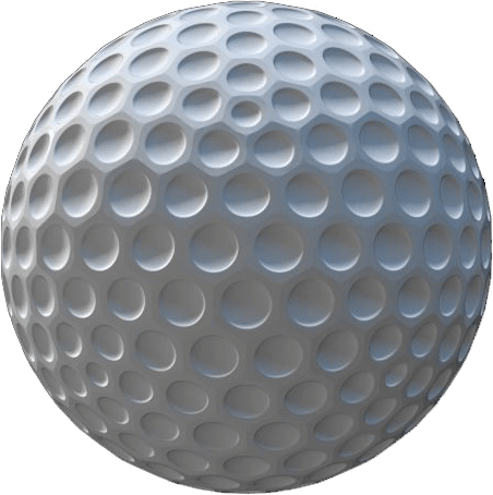
If we swapped out the golf ball for one with a larger radius, like a baseball, then our arc would be shallower, since more of the ball is sitting above the hole:

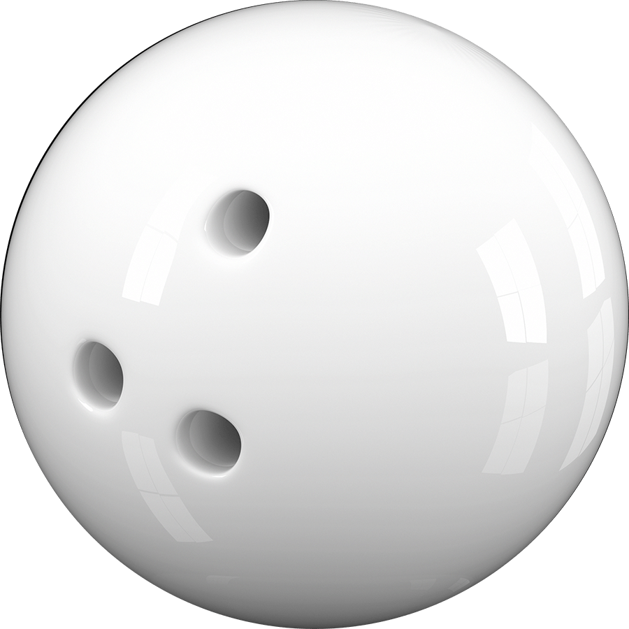
And if we chose an enormous ball like a bowling ball, the arc would practically be flat:
To bring this back to SVGs: when we draw an arc, we need to specify a horizontal radius (rx) and a vertical radius (ry). These values affect the size of the hypothetical ellipse, which in turn affects how deep/shallow the arc is. The smaller the radius, the deeper the arc.
Link to this headingLarge vs small arcs
Let’s suppose we want to draw an arc between these points with a rx/ry of 5:
As we saw above, the browser creates a hypothetical ellipse with the provided radius and finds a way to bridge the gap using it, like this:
But wait a sec: there are two separate paths we could follow, to get from the start point to the end point. We could take the short route going down, or the long way around, going up.
Try toggling the “Arc size” to see what I mean:
You can also drag the handles around to see how this flag behaves with different gaps.
Whenever two points are connected with a hypothetical ellipse, there are two routes we could take. We can pick which option we want with the “large arc flag” parameter. It’s a binary value: 0 selects the short path, 1 selects the longer path.
Link to this headingPicking the right ellipse
Once again, let’s start with a hypothetical scenario about a hypothetical ellipse:
In this case, the circle’s diameter is exactly equal to the gap between points, and so there’s only one possible ellipse that can work in this scenario.
But check this out: suppose we increase the radius of this ellipse so that it’s a bit bigger than the gap:
In this case, there’s actually two places I can put this ellipse:
We can select which ellipse we want to use with the “sweep flag”. Like the large arc flag we saw above, it’s a binary value: 0 selects the counter-clockwise arc, 1 selects the clockwise arc.
You can see the resulting arc here:
Link to this headingRotation
We’re almost done, I promise! There’s only one more parameter we need to look at.
This final parameter, rotation, lets us rotate the arc:
More specifically, this parameter rotates the hypothetical ellipse, and it does this before trying to figure out how to connect the two points using this ellipse.
If your arc is circular (when rx and ry are set to the same value), this property has no effect. This makes sense when we imagine rotating a perfect circle: the rotation is totally invisible.
Now, I’ll be honest with you: I don’t think I’ve ever actually used this parameter. 😅
The main use case I see for this property is to correctly align the ellipse with the rest of the path. So, for example, if we’re drawing a cowboy hat at a 45-degree angle, we can apply the same rotation to the ellipse:
I think the reason I never find myself needing this is that I wouldn’t try to draw something at an angle like this. I would prefer to draw it straight-on and then rotate the entire shape using transforms. I suppose this could be useful if our path needed to draw multiple things at different angles, but at that point, I’d prefer to create it using drawing software instead of code.
So, if your brain is feeling overloaded, feel free to not worry about “rotation”! Set this value to 0 and ride off into the sunset. 🤠
Link to this headingRevisiting the syntax
I told you arcs were complicated!
Here’s that syntax we started with. Hopefully, with all this new context, it makes a lot more sense:
<path
  d="
    M [start-x],[start-y]
    A [rx],[ry] [rotation] [large-arc-flag] [sweep-flag] [end-x],[end-y]
  "
/>
Here’s a quick cheatsheet of what each parameter does:
- The arc starts where the previous command left off. The arc’s start position is inherited from that previous command.
rxandrycontrol the horizontal/vertical radius of the hypothetical ellipse.rotationwill rotate the hypothetical ellipse. Specified in degrees. Leave as 0 for no rotation.large-arc-flagis a binary value that controls whether the arc takes the short path (0) or the long path (1). Has no effect if both paths are the exact same length.sweep-flagis a binary value that controls which ellipse is used. From the start point, we can either go counter-clockwise (0) or clockwise (1).end-xandend-yselects the end point for our arc.
All of these parameters are required. Even if you don’t want to rotate your arc, for example, you still need to set rotation to "0".
Here’s a playground for you to experiment with these concepts yourself:
Code Playground
<svg viewBox="0 0 16 16">
  <path
    d="
      M 2,2
      L 5,5
      A 4,4 0 0 0 11,11
      L 14,14
    "
  />
</svg>
Link to this headingAnimations
At this point, we’ve covered all of the most important fundamentals of SVG paths. I have a few more useful tidbits to share with you, but first, I want to let you know about a thing I’ve been working on. 😄
It’s called Whimsical Animations(opens in new tab), and it’s a comprehensive interactive course about creating next-level animations and interactions.

The course is split into four parts, covering a wide range of animation techniques. Part 2 is all about SVG animation. You’ll learn how to animate the paths we’ve been working with in this post, to create wonderful micro-interactions and big splashy effects. If you’re finding this blog post useful, you’ll get so much out of the course!
Registration is now open! You can find out more here:
If you’ve ever wondered how I made something on this blog, there’s a very good chance that we cover the underlying techniques in the course. My goal is to share all of my secrets, stuff that took me years and years to figure out on my own.
Link to this headingLil’ extras
SVG paths have a few little bits of syntactic sugar, things that make it a bit easier to work with.
Link to this headingClosing paths
By default, paths are open-ended, but we can instruct our path to seal itself up using the Z command:
Code Playground
<svg viewBox="0 0 16 16">
  <path
    d="
      M 4,4
      L 4,12
      L 12,12
      Z
    "
  />
</svg>
The Z command will draw a straight line back to the first point specified by the original M command. It’s equivalent, in this case, to L 4,4.
Link to this headingRelative commands
In this blog post, we’ve been using uppercase commands like L and A. Each command has a lowercase alternative:
Code Playground
<svg viewBox="0 0 16 16">
  <path
    d="
      M 4,4
      l 4,8
      l 4,-8
    "
  />
</svg>
The lowercase variants are relative commands. Instead of specifying coordinates based on the SVG coordinate system (with (0, 0) being in the top-left corner), relative commands are anchored to the previous command’s position.
So, in the example above, we start by moving to (4, 4). We then draw a relative line that adds 4px horizontally and 8px vertically. These values are added to the command’s starting position. The ending X value will be 8 (4 + 4), and the ending Y value will be 12 (4 + 8), so this command is equivalent to L 8,12.
Similarly, negative values move in the opposite direction. The final command is another relative line that adds another 4px to the X coordinate (8 + 4 = 12), but subtracts 8 from the Y coordinate (12 - 8 = 4).
Relative commands provide an entirely different mental model for designing paths, and it can be useful for certain kinds of illustrations. It also makes it easier to shift things along as a group:
Relative commands will automatically adapt when their anchor point changes, so we wind up sliding the path around rather than deforming it.
That said, I don’t really find myself doing this much, in practice. Instead, I typically solve this problem with a transform: translate(x, y), to slide the path around wherever I want.
Link to this headingChained curves
If you’ve ever tried to chain Bézier curves together, you’ve likely found that it’s challenging to get it to look right:
Code Playground
<svg viewBox="0 0 16 16">
  <path
    d="
      M 4,4
      Q 4,10
        8,8
      Q 14,0
        12,12
    "
  />
</svg>
If you look closely, there’s a visible “elbow” where the two curves connect:

In order for our Bézier curves to flow well, we need to match the angles of subsequent curves, so that the path doesn’t veer off in a new direction. There isn’t any sort of built-in smoothing.
Fortunately, there is a handy command that can help:
Code Playground
<svg viewBox="0 0 16 16">
  <path
    d="
      M 4,4
      Q 4,10
        8,8
      T 12,12
    "
  />
</svg>
The T command creates a Quadratic Bézier curve, like Q, but it doesn’t take a control point, it only accepts an end point. The control point is derived automatically by mirroring the angle, so that our path is smooth and kink-free.
Similarly, the S command creates a cubic Bézier curve that omits the first control point. That point will be computed automatically to ensure a smooth curve.
For example:
Code Playground
<svg viewBox="0 0 24 16">
  <path
    d="
      M 0,8
      C 4,0
        8,21
        12,12
      S 16,16
        24,8
    "
  />
</svg>
This is a useful bit of syntactic sugar because it saves us the trial and error of finding a control point that doesn’t result in an elbow. In practice, though, I generally find myself using vector graphics software if my shape includes many chained curves (like the cloud swoops at the top of this page).
Like so many of my blog posts, this one turned out to be way longer than I originally intended, and yet it still only scratches the surface of what can be done with SVG paths. 😅
Like I mentioned above, you can learn so much more in my brand-new course, Whimsical Animations(opens in new tab).
Last updated on
June 9th, 2026